
The SP PRO Managed AC Coupling,
provides a method of linking
Selectronic Certified (SCERT) Solar Inverters inverters to the
SP PRO via the AC Load
supply. Regardless
of whether the grid or a generator
is connected, the SP PRO can
manage and control SCERT
inverters.
This document applies to SCERT GEN24 Fronius Primo inverters
which have been pre-configured and
programmed by Selectronic,
as well as the steps needed to install
a managed AC Coupled system. GEN24 SCERT
inverters can be identified by a
sticker
on the front of the
product.
Each inverter must be installed as
per their
individual installation instructions
with the additional allowance for
communications cables linking all of
the inverters together.
Note: This
document needs to be read in
conjunction with
the SP PRO Instruction
Manual
1. Compatibility Table
| SP
PRO
System | Primo
GEN24
SCERT |
| SP PRO Series I single
phase | No |
| SP PRO Series II single
phase | No |
| SP PRO Series II three
phase
(legacy) | No |
| SP PRO Series II with
Advanced Comms
card, single, split or
three
phase
Powerchain. | Yes* |
| SP PRO
Series 2i single, split or
three
phase
Powerchain. | Yes* |
- Only make adjustments to the
Primo GEN24 configuration as indicated in this document.
- The Fronius SnapINverter Primo and GEN24 cannot be connected to the same SP PRO.
- The SP PRO and Fronius GEN24
SCERT Managed AC coupling cannot be used with a Fronius Smart Meter.
- For a Solar Hybrid (grid connected) system, the minimum capacity of the battery connected to the SP PRO varies depending on SP PRO model and the battery type. When the system is islanded (e.g. during a grid outage) the SP PRO will limit the output of the AC coupled solar based on the installed battery size.
- For an Off-Grid system, the
minimum capacity of the battery
connected to the SP PRO
varies
depending on SP PRO model,
the battery type and the
total rating of all the connected
Fronius GEN24
SCERT inverters.
The
following table
summarizes the steps
taken to set up a Fronius
SCERT in a
Managed AC Coupled system.
Once the system has been
installed, use the table to
check that each step has been
completed.
Refer
to the pages following the
tables for detailed
information on each of the
installation
steps.
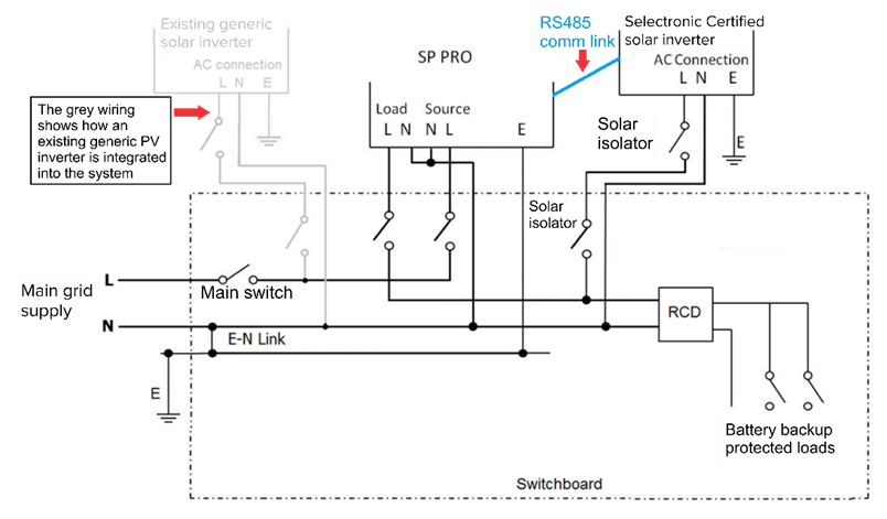
The diagram below shows a managed AC
coupled system with
five Fronius GEN24 Primos.
3. System
Requirements
To successfully
install a SP PRO Series 2i
Fronius GEN24 SCERT managed system,
there are
particular system requirements that
need to be met.
- The maximum SCERT Solar Inverter capacity should be no greater than 2 x the SP PRO continuous rating. This may be reduced further depending on your battery size or Electricity company allowances for On Grid systems.
- The SP PRO / Comm board
must have firmware version 15.23 /
5.02 or higher.
- The
Fronius inverters must be
Selectronic Certified
(SCERT).
- Fronius
Primo "Snap On" and Gen24 cannot
be controlled by the same System
or Phase manager.
- Maximum
of five Fronius Primo Gen24 SCERTs
per SP PRO Manager in a
single phase system. Worker units are not able
to control SCERT
inverters.
- Maximum
of fifteen (five SCERTs per
SP PRO Manager) Fronius Gen24
SCERTs in a three
phase system. Worker units are not able
to control SCERT
inverters.
To
configure the SP PRO - Fronius
system, the Site Configuration Wizard
in SP
LINK’s Easy Start Guide must be
used.
Only SP PRO 2i (Revision
22) and above or Revision 20 and above
when fitted with Advanced Comms
Cards, are supported for Fronius GEN24 Primo
SCERT.
- On-grid: The GEN24 Primo is compatible with SP PRO Series 2i configured as On-grid AS/NZS 4777.2:2020, with the following models only - SPMC480-AU, SPMC481-AU, SPMC482-AU, SPLC1200 and
SPLC1202. Off-grid: The GEN24 Primo is compatible with any SP PRO Series 2i model configured as Off-grid.
- SP PRO / Comm card Software
Version 15.23 / 5.02 or higher is
required.
- Older revisions of firmware
must be updated.
- Carry out a Reset to Factory defaults
on all SP PRO inverters after a
firmware update.
- Configure the SP PRO inverters after
the Reset to Factory defaults.
To check firmware revision
run SP LINK, connect to the
SP PRO and go to:
The Fronius
inverter must be Selectronic
Certified. Other Fronius inverters
will not
operate correctly.

It is good practice to number each Fronius
GEN24 SCERT from
1 up to 5 so that each inverter can be
easily referenced within SP LINK.
In a multiphase system, label each Fronius
GEN24 Primo SCERT
connected to L1, from L1-1 to L1-5. Do the
same for each of the Fronius Primos
connected to L2, from L2-1 to L2-5, and so
on.
This number 1 to 5 is used for the
communications link
addressing. See Configuration
section.
5. Fronius AC wiring
Primo
For
correct and
safe operation, the Fronius AC output
wiring must be connected to the AC
Load
terminals of the SP PRO in
accordance with local wiring
rules.
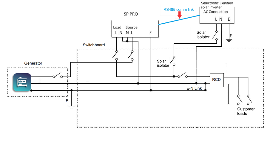
Fronius
AC Wiring guide for Off Grid
installation
Note: The
system will not function correctly if
the Fronius Primos are installed on
the AC Source side of the
SP PRO.
The communication link always starts at the
SP PRO, then daisy-chains to all Fronius
SCERTs in the system.
7. Connection to GEN24 SCERT
Series 2i
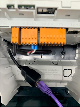
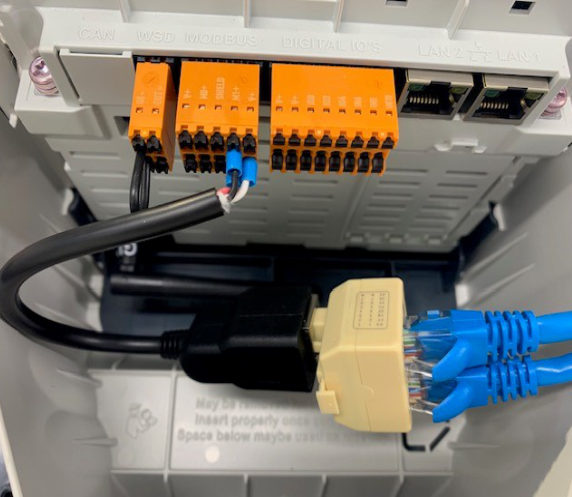
Note: The RJ45 adapter
cable comes connected to the Data Manager
Connector within the Fronius
SCERT.
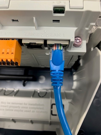
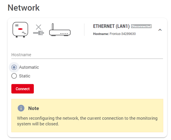
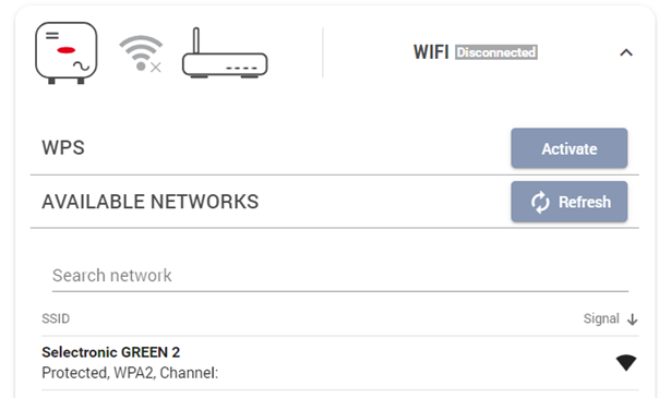
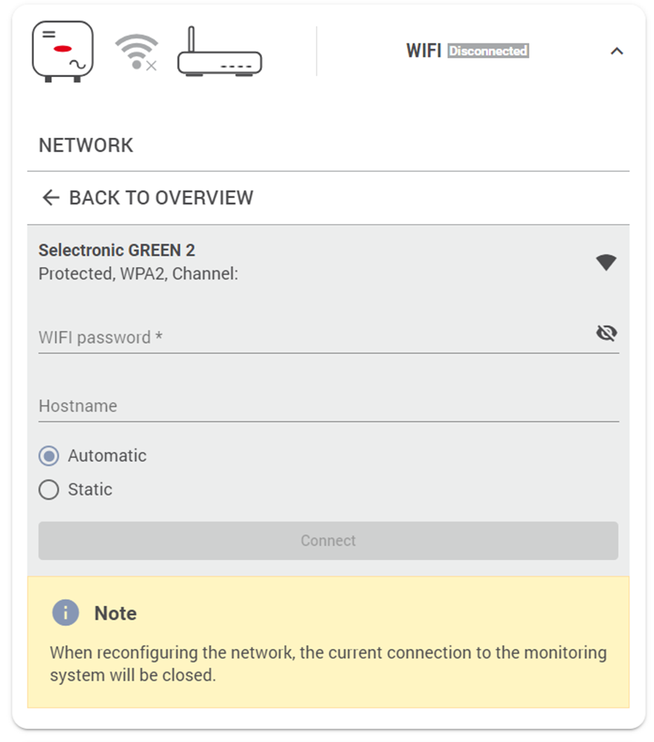
Configuration of the network settings
allows for access to web
interface without using access point and
for integration to Solar.web.
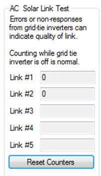
- Check that all the communication cables have been connected correctly.
- In the Service Settings tab
click the 'Reset Counters' button
Wait 2 minutes and check that the error count remains at zero for all the connected Fronius SCERTs.
An
error count of 5 or less per minute is
acceptable but, in this case, it is
good
practice to check the wiring and that
the termination resistors are set
correctly in the SP PRO and
Fronius SCERTs.
Once the
Communications link has been verified
for each Fronius SCERT, switch the DC
feeds to each inverter on and perform
the verification steps
below.
When a Fronius SCERT
loses communications with the
SP PRO, the output of the
Fronius SCERT will drop to zero power after 10
seconds.
Go to INFO > Readings menu on the front
display of the first Fronius SCERT and
check that the external limit (ext.
Lim.) drops to 0%.
The following steps are for when Selectronic Certified SCERT Fronius units are installed without an SP PRO,
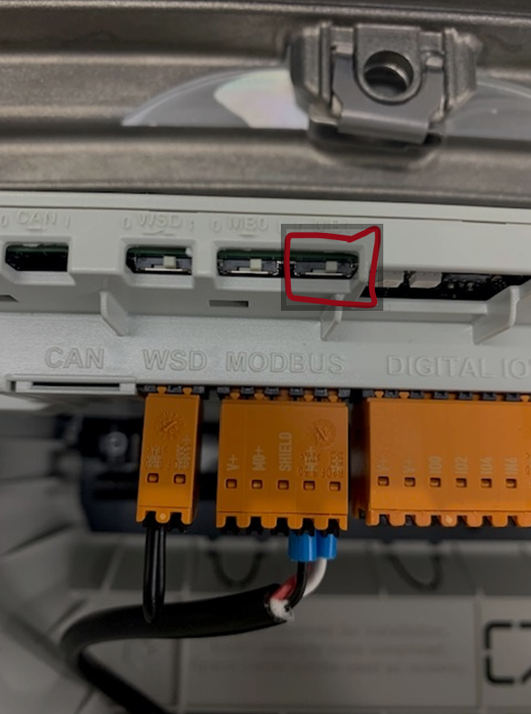
A link must be fitted to the orange “Digital I/Os Connector” from the “V+” pin to IO “2” pin so that Fronius SCERTs can produce full power.
The country code must be set to AU – Australia. Access the Fronius web interface – see Fronius instruction manual. Login as Technician with the password provided with each Fronius Gen24. Navigate to “Safety and Grid Regulations” -> “Country Setup” and enter the code which may be obtained by contacting Fronius directly. Set the Country / Region to Australia and the Grid Code appropriately.
The following steps are for when Export Limitation is required for a Selectronic Certified SCERT Fronius units installed without an SP PRO. Refer to the Fronius instruction manual for details of export power limitations.
Set the country code as described in section xxx but DO NOT fit the wire link.
Access the Fronius web interface – see Fronius instruction manual. Login as Technician with the password provided with each Fronius Gen24. Navigate to “Safety and Grid Regulations” -> “Export Limitation”. Set the export limitation as required.
Navigate to “Safety and Grid Regulations” -> “I/O Power Management”. Disable Rule 1 and click “Save”.
If the system is later installed with an SP Pro this rule MUST be re-enabled.
Additional Information: