

Installation Note: IN0048 - Rev 04
Contents:
- Applicability
- Overview
- Wireless link restrictions
- Extending the Wireless Range
- Installation
- Connection from the SP PRO series I to Local Wireless RS485 device(s)
- Single Phase SP PRO connection to Local Wireless
RS485 device
- Multi Phase Installation: SP PRO, Local Wireless RS485 device (Series
II only)
- Remote Wireless RS485 device and Fronius
Inverters
- Configuration settings for SP PRO / Fronius
managed AC coupling
Introduction
This document outlines the
steps required to install a wireless Managed AC Coupled system with a Fronius
Selectronic Certified grid inverter.
1. Applicability
- Suitable for all Selectronic Certified Fronius Inverters
- Suitable for Selectronic SP PRO Series II in single phase systems
- Suitable for Selectronic SP PRO Series II in three phase or dual phase systems
- Suitable
for Selectronic SP PRO Series I in single phase systems ONLY. Need additional
product “Adaptor, SP PRO series I to SCERT”, stock code 005077
A summary of the
installation steps are:
- Install the SP PRO and Fronius Inverters according to the SP PRO and Fronius installation manuals.
- Connect the Selectronic RS485 wireless link devices to the SP PRO.
- Connect the other half of the Selectronic RS485 wireless link devices to the first Fronius inverter in the system.
- Connect power, via the plug packs, to all the RS485 wireless devices.
- Provide a hardwire connection between the first Fronius inverter and subsequent Fronius inverters on that phase.
- Configure
the Fronius inverter(s) and SP PRO(s) according to the document IN0042_xx SP
PRO Fronius Managed AC Coupling Installation Notes or for Series 1 IN0045_xx SP
PRO Series I Fronius Managed AC Coupling Installation Notes.
This document needs to be read in conjunction with IN0042_xx SP PRO Fronius
Managed AC Coupling Installation Notes or for Series 1 IN0045_xx SP PRO Series
I Fronius Managed AC Coupling Installation Notes. and the SP PRO AU or GO
Series Instruction Manual.
2. Overview
The diagram below (fig. 1)
shows a typical single phase managed AC coupled system with one Fronius inverter.
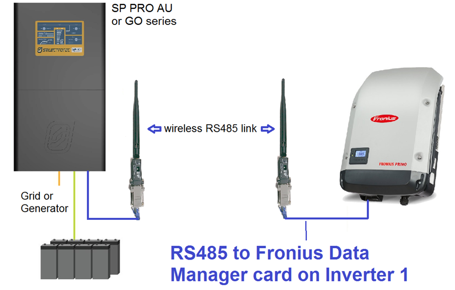
Fig. 1 –
Overview of single phase system using the Wireless RS485 – One Fronius Inverter
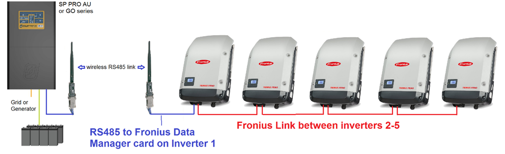
Fig. 2 –
Overview of single phase system using the Wireless RS485 – Five Fronius
inverters
The diagram below (fig. 3)
shows a typical three phase managed AC coupled system with one Fronius inverter
per phase.
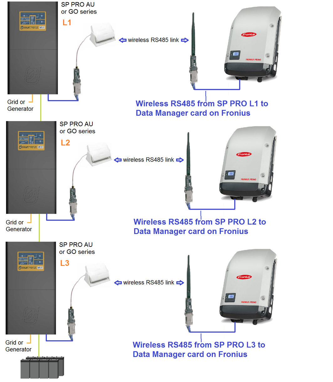
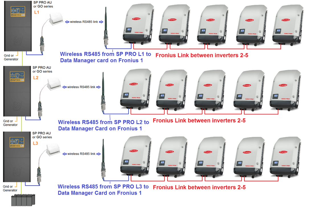
Diagram below (fig 4) shows a larger three phase system with five Fronius connected.
Note: Only one (Master)
per phase is connected with wireless, and the four others (Slaves) on each
phase are connected with the Fronius Link.
In a three phase or dual phase
system, a patch antenna must be installed on each of the wireless RS485 devices
at each of the SP PRO inverters. The minimum separation distance between patch
antennas for different phases is 1 metre.
3. Wireless link restrictions
The wireless link uses the
same frequency band as WiFi (2.4GHz). Any obstructions between the two devices
or interference from other devices using the same frequency band (other Bluetooth
or WiFi devices) will have a significant impact on their range.
To achieve the maximum
range of 200m there must be line of sight between the two devices with no
interference. As a rule of thumb, each obstruction that is equivalent to a stud
wall will reduce the distance by about 20%. Mud brick walls, double brick or
concrete walls will have a much larger impact on the range.
Any obstruction from the
landscape such as levy banks, hills or undulating land will totally block the
signal so the wireless link will not function.
If more than one wireless
link is required within the same installation (such as a three phase system),
then the interference between the devices will further reduce the distance. In
this case patch antenna must be used on the SP PRO end of link and recommended
at Fronius End of the link.
Separate multiple antennas
by at least 1m to assist in reducing interference.
4. Extending the Wireless Range
If the required distance
is longer than the specified 200m clear line of sight, or there is multiple
devices being used then the range of the devices can be extended by replacing
the dipole antenna with a “patch” antenna. The table 1 below gives an
indication of the expected range when using a combination of dipole and patch
antennas:
Table 1: Maximum “Line of sight” distance between
Wireless RS485 device pairs.
Wireless
device antenna at Fronius | Max distance,
one pair of devices, line of sight (single phase) | Max distance,
multiple pair of devices, line of sight (dual phase or 3 phase) |
Dipole (supplied) | Dipole (supplied) | 200m | Not recommended |
Patch – Optional (stock code 004810) | Dipole (supplied) | 300m | 150m |
Patch – Optional (stock code 004810) | Patch – Optional (stock code 004810) | 500m | 250m |
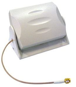 | Optional Patch Antenna to
extend the range of the wireless devices. Please order Selectronic Stock code
004810. |
5. Installation
Connection from the SP PRO series II to
Local Wireless RS485 device(s)
Install the AC coupled
interface card into the SP PRO inverter (or each inverter in a multiphase
system) following the instructions in IN0042_xx
SP PRO Fronius Managed AC Coupling Installation Notes.
Using the supplied ‘CAT5’ network
cable, plug one end into the AC coupled interface card and the other end onto
the RS485 wireless adaptor as shown below. If a longer cable is required, then
this can be any ‘Cat 5’ cable (network patch lead). 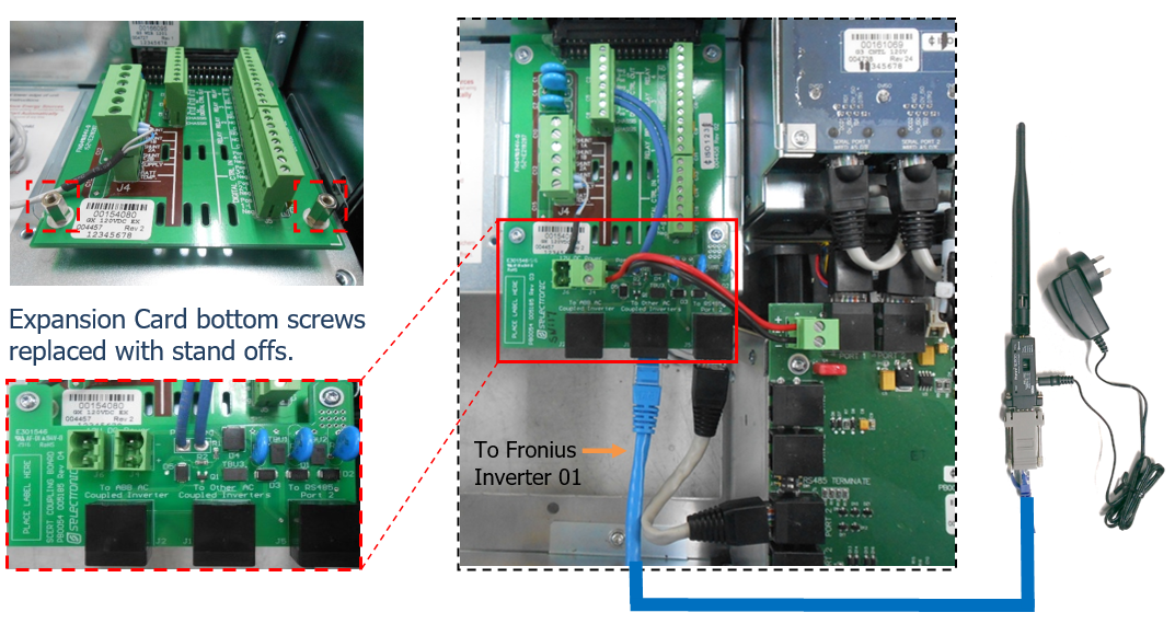
6. Connection from the SP PRO series I to Local Wireless RS485 device(s)
Must use the 'Adaptor, SP PRO series I to
SCERT' - stock code 005077.
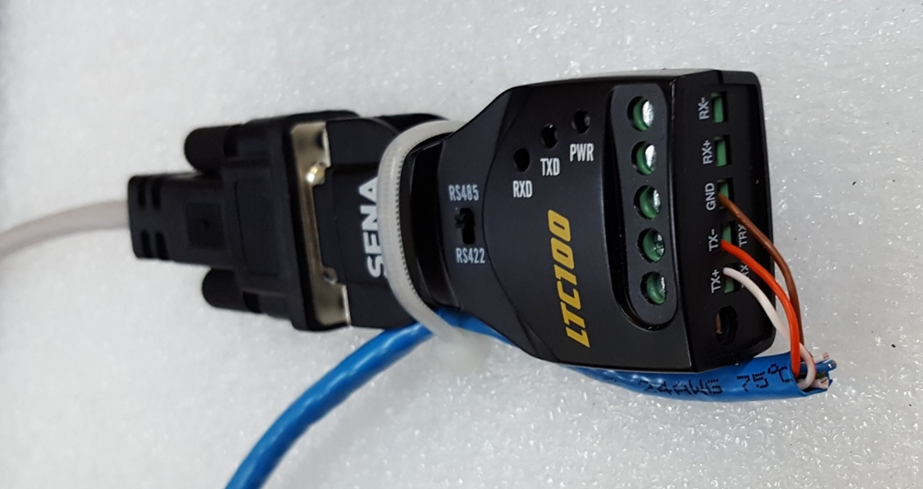
Connect the wires as
follows to the LTC100 found in the “Adaptor, SP PRO series I to SCERT” kit. The
other end of the network cable connects to
the RS485 Wireless adaptor.
Use a cable tie as a
strain relief for the network cable as required.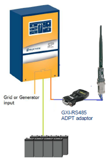
Cat 5 wire
colour | Terminal on
the LTC100 |
Brown | GRND |
Orange | TX- |
Orange/White | TX+ |
7. Single Phase SP PRO connection to Local Wireless
RS485 device
The plug packs must be
connected to the same AC power circuit as the connected Fronius inverters. This
is normally the AC load side of the SP PRO.
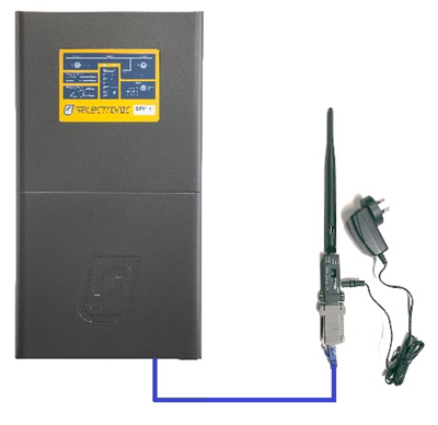
Fig. 5 – Communications
wiring with SP PRO
8. Multi Phase Installation: SP PRO, Local Wireless RS485 device (Series
II only)
To incorporate the
Wireless RS485 devices in a multi-phase (three phase or split phase) Managed AC
coupled system, one Wireless RS485 device pair is installed per phase.
In this configuration
there will be one Wireless RS485 device attached to each of the SP PRO
inverters. At the remote end, the matching Wireless RS485 device will only be
connected to the Fronius inverters for that phase.
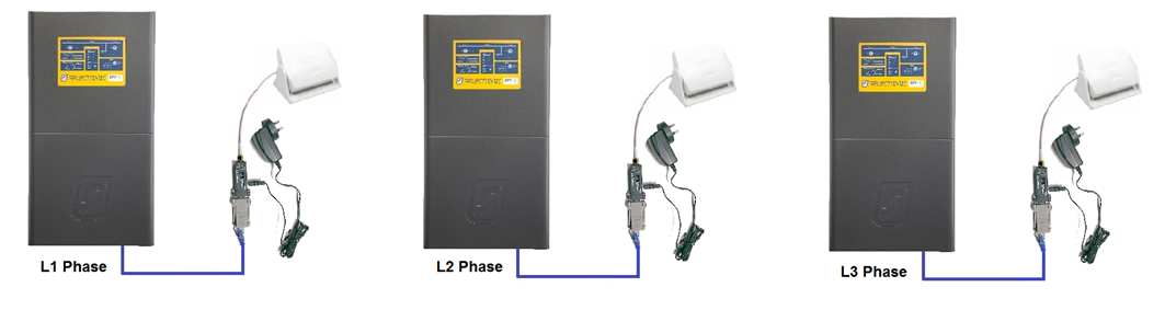
Fig. 6 –
Communications wiring for local Wireless RS485 Adaptors in a three phase
system.
Maintain at least 1m
separation between each phase’s Patch Antennas, to reduce interference.
9. Remote Wireless RS485 device and Fronius
Inverters
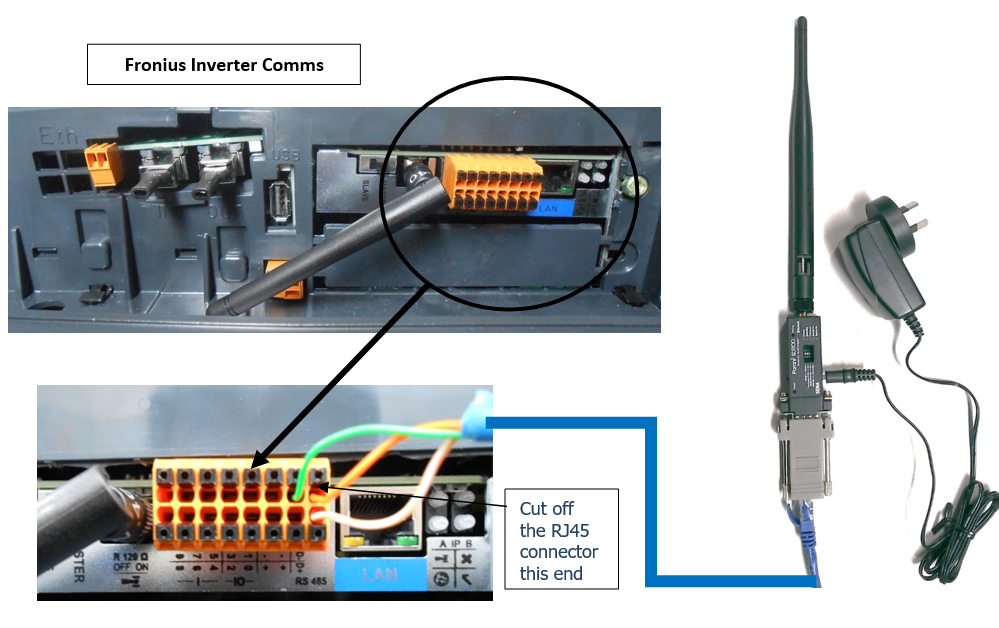
Now connect the wireless
RS485 device to the Fronius inverter 1 using the supplied patch lead. One end
of the patch lead plugs into the RS485 wireless device, the other end has the
wires stripped and connected to the Fronius Inverter Comms connector (See Fig
8).
See IN0042_xx SP PRO Fronius Managed AC Coupling Installation Notes for
connection details to the Fronius inverter.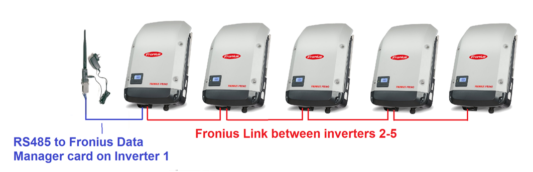
10. Configuration settings for SP PRO / Fronius
managed AC coupling
Refer to the installation instructions IN0042_xx 005230 SP PRO Fronius Managed AC Coupling Installation Notes for information on setting up and
commissioning the inverters.
Additional Information